Now that all the construction is complete, it's time to get into the control!
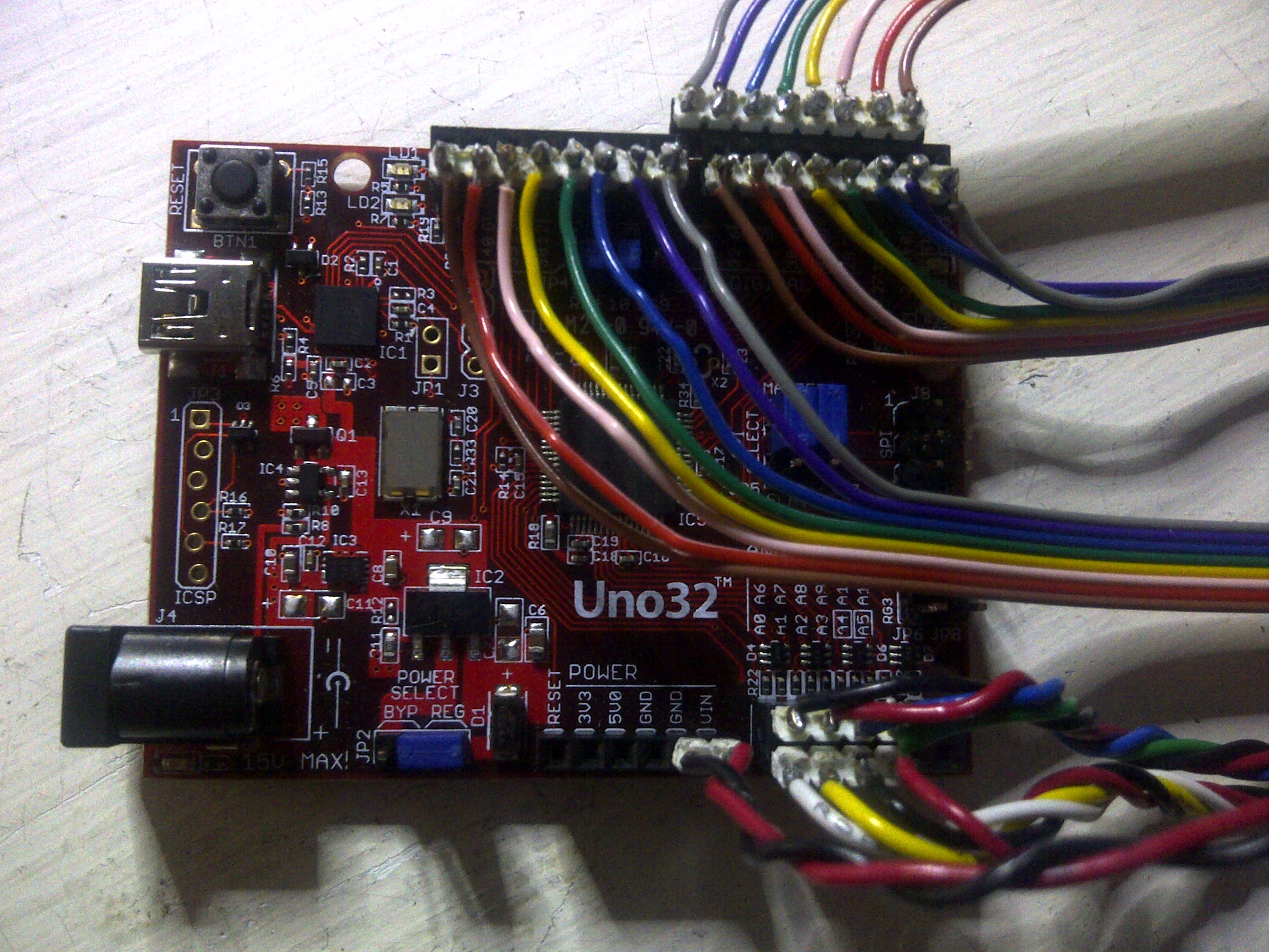
Rather than buying a micro-controller chip, crystal & all the extra bits and pieces and having to build that circuit as well, I decided to use an "off-the-shelf" Arduino style control board. The Arduino Uno was my original thought, but then I saw the ChipKit Uno32 that used the Arduino development environment but had MORE I/O (42 compared to 20) and ran at a higher frequency, at very little extra cost.
Thus, I was able to use 3 sets of 8 outputs to drive the main LED outputs (ie: the top 3 connections in the picture) with 4 additional outputs used to do the Row selection (half of the bottom right connections) and the final 4 additional outputs (other half of the bottom right connections) being used for the Level selection.
The last two wires were simply to connect the power supply of the control board with the supply on the custom made control board. This meant that I could plug an external 5V supply into the controller or the control board or BOTH! As 512 LEDs at 3x20ma each could potentially draw as much as 30A if they were all on at the same time, I figured it was worth being able to connect more than one 5V plug pack ;-)
All jumpers on the board stayed in their default positions.
Only other thing worth mentioning is the USB connection - this was used to download the program and would provide enough power to run the micro-controller, but not much more. The LEDs did work dimply, but I needed to plug a 5V adapter into the DC input jack on the micro-controller or the custom control board to get the LEDs to work nicely.
After a bit of playing, I finally decide on a program that was amazingly simple...
Setup
// Configure the I/O as outputs
// Load the first step, pattern & speed

Loop
// If step changed, load the LED pattern from PROGRAM memory
  // Get the LED pattern
  // Get the next step number
  // If next step is zero, make current step the last

// Drive the LEDs level by level
  // Unselect all levels [All LEDs will be off]
  // Set the level selection bits
  // Transfer the entire level's pattern into the buffer chips row by row
    // Set the row selection bits
    // Set the individual LEDs
    // Minor pause to make sure the pins are set
    // Transfer the LED states into the selected row's buffer [buffer outputs are cleared  while this happens]
    // Minor pause to make sure the pin is set
  // Minor pause to make sure the pins are set
  // Turn the selected level on and keep them on for a specified time
// Track the repeat count and increment the animation step when required
Which is basically...
- Load a block of memory for the entire 8x8x8 matrix from a predefined animation table
- Step through the block of memory setting the desired outputs, as per the predefined animation table
- Clear the level
- Load the 192 output signals
- Display the level
- Loop until the next step is reached and start the process again
The only thing left to do was to define the "predefined animation table". After doing a few manual versions, I created an Excel spreadsheet that allowed me to enter the colour of the LED I wanted in a particular location and it gave me the memory map that would give that display.
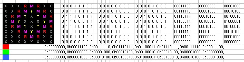
All I had to do after that was to decide on what pattern I wanted on each Level and copy the memory map for that level into the "predefined animation table".
const unsigned char maAnimation[] = {
                                    // Speed / Step
                                      12,
                                      // RED Column * Row * Level
                                        0b00000000, 0b00000001, 0b00000000, 0b00000000, 0b00000000, 0b00000000, 0b00000000, 0b00000000,
                                        0b00000010, 0b00000100, 0b00000010, 0b00000001, 0b00000000, 0b00000000, 0b00000000, 0b00000000,
                                        0b00011000, 0b00010000, 0b00011000, 0b00000100, 0b00000010, 0b00000011, 0b00000000, 0b00000000,
                                        0b00001000, 0b00010000, 0b00001000, 0b00000100, 0b00000010, 0b00000001, 0b00000000, 0b00000000,
                                        0b00011000, 0b00010000, 0b00011000, 0b00000100, 0b00000010, 0b00000011, 0b00000000, 0b00000000,
                                        0b00000010, 0b00000100, 0b00000010, 0b00000001, 0b00000000, 0b00000000, 0b00000000, 0b00000000,
                                        0b00000000, 0b00000001, 0b00000000, 0b00000000, 0b00000000, 0b00000000, 0b00000000, 0b00000000,
                                        0b00000000, 0b00000000, 0b00000000, 0b00000000, 0b00000000, 0b00000000, 0b00000000, 0b00000000,
                                      // GREEN Column * Row * Level
                                        0b00000001, 0b00000011, 0b00000001, 0b00000000, 0b00000000, 0b00000000, 0b00000000, 0b00000000,
                                        0b00000110, 0b00001100, 0b00000110, 0b00000011, 0b00000001, 0b00000000, 0b00000000, 0b00000000,
                                        0b00011000, 0b00010000, 0b00011000, 0b00001100, 0b00000110, 0b00000011, 0b00000000, 0b00000000,
                                        0b00011000, 0b00010000, 0b00011000, 0b00001100, 0b00000110, 0b00000011, 0b00000000, 0b00000000,
                                        0b00011000, 0b00010000, 0b00011000, 0b00001100, 0b00000110, 0b00000011, 0b00000000, 0b00000000,
                                        0b00000110, 0b00001100, 0b00000110, 0b00000011, 0b00000001, 0b00000000, 0b00000000, 0b00000000,
                                        0b00000001, 0b00000011, 0b00000001, 0b00000000, 0b00000000, 0b00000000, 0b00000000, 0b00000000,
                                        0b00000000, 0b00000000, 0b00000000, 0b00000000, 0b00000000, 0b00000000, 0b00000000, 0b00000000,
                                      // BLUE Column * Row * Level
                                        0b00000001, 0b00000010, 0b00000001, 0b00000000, 0b00000000, 0b00000000, 0b00000000, 0b00000000,
                                        0b00000100, 0b00001000, 0b00000100, 0b00000010, 0b00000001, 0b00000000, 0b00000000, 0b00000000,
                                        0b00000000, 0b00000000, 0b00000000, 0b00001000, 0b00000100, 0b00000000, 0b00000000, 0b00000000,
                                        0b00010000, 0b00000000, 0b00010000, 0b00001000, 0b00000100, 0b00000010, 0b00000000, 0b00000000,
                                        0b00000000, 0b00000000, 0b00000000, 0b00001000, 0b00000100, 0b00000000, 0b00000000, 0b00000000,
                                        0b00000100, 0b00001000, 0b00000100, 0b00000010, 0b00000001, 0b00000000, 0b00000000, 0b00000000,
                                        0b00000001, 0b00000010, 0b00000001, 0b00000000, 0b00000000, 0b00000000, 0b00000000, 0b00000000,
                                        0b00000000, 0b00000000, 0b00000000, 0b00000000, 0b00000000, 0b00000000, 0b00000000, 0b00000000,
                                    // Repeat: Step, Red, Blue, Green as required
                                    // Last step
                                      0
                                    };
Finally, compiled the code with the predefined animation table I copied straight from Excel and download it to the micro-controller!
Job done - Animations created as per the videos shown in the introduction!