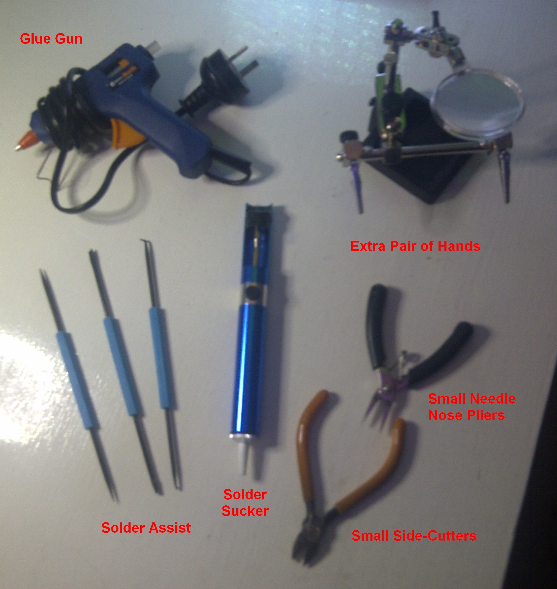
With ~2,000 solder joints, the LED matrix is the most tedious part of the job and the logical place to start, once you have the LEDs a good soldering iron and some helpful tools!
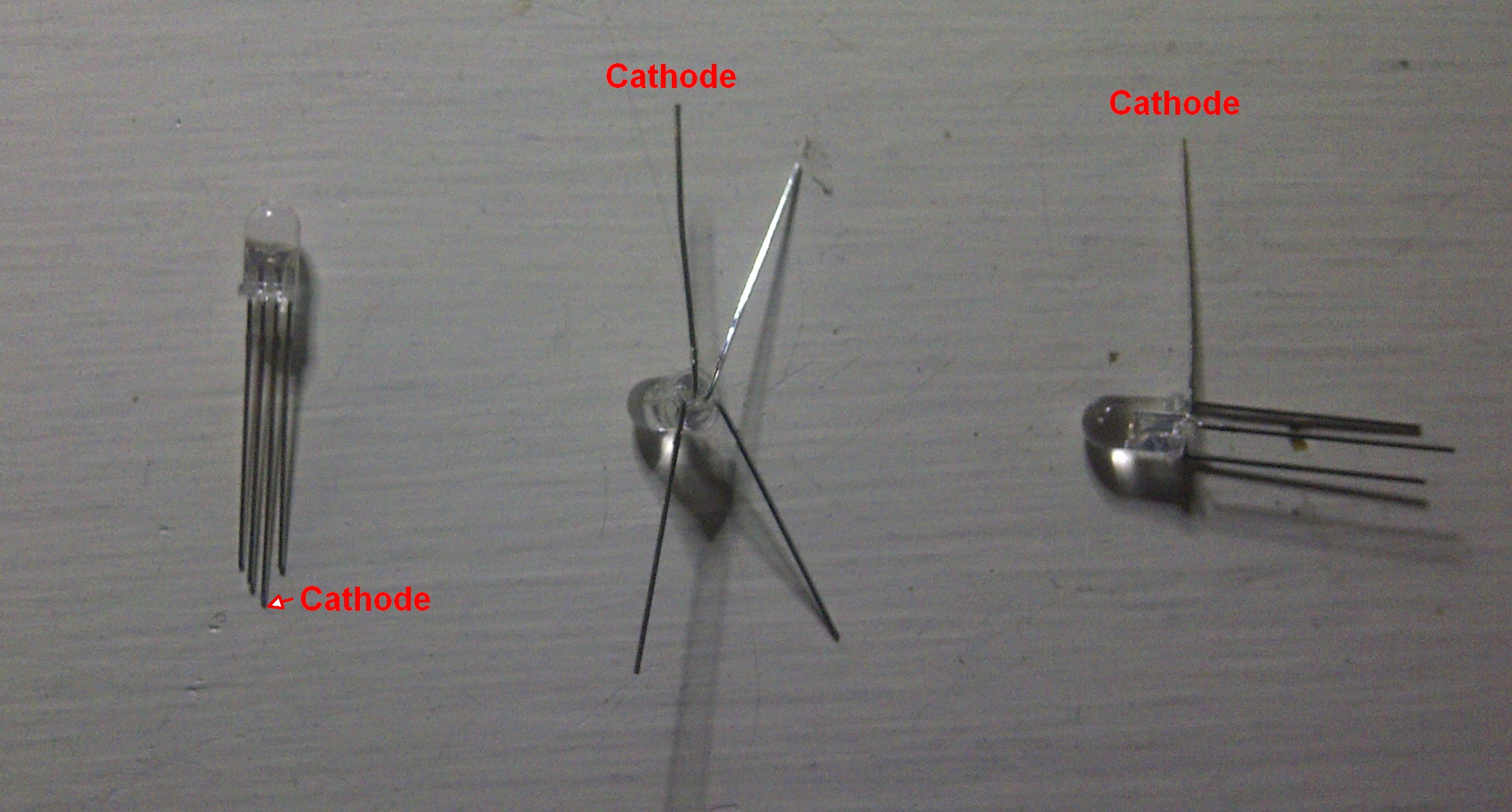
I used common Cathode (connect to ground) LEDs but common Anode ones would also be possible, although they would require a slight change to the circuit design & code.
Spread all the pins on the LED so the base of the LED is flat - Bend the Cathode at a right angle to the line of the pins and try to bend the other pins so that points where they all cross the circumference of the LED forms a square. Then turn the R, G & B pins back the way they were originally, but from the edge of the LED so that you can position a LED directly underneath - Make sure you do it the same way for every other LED!
Note: Try to only bend the pins once in each location as they can snap off if over-worked.
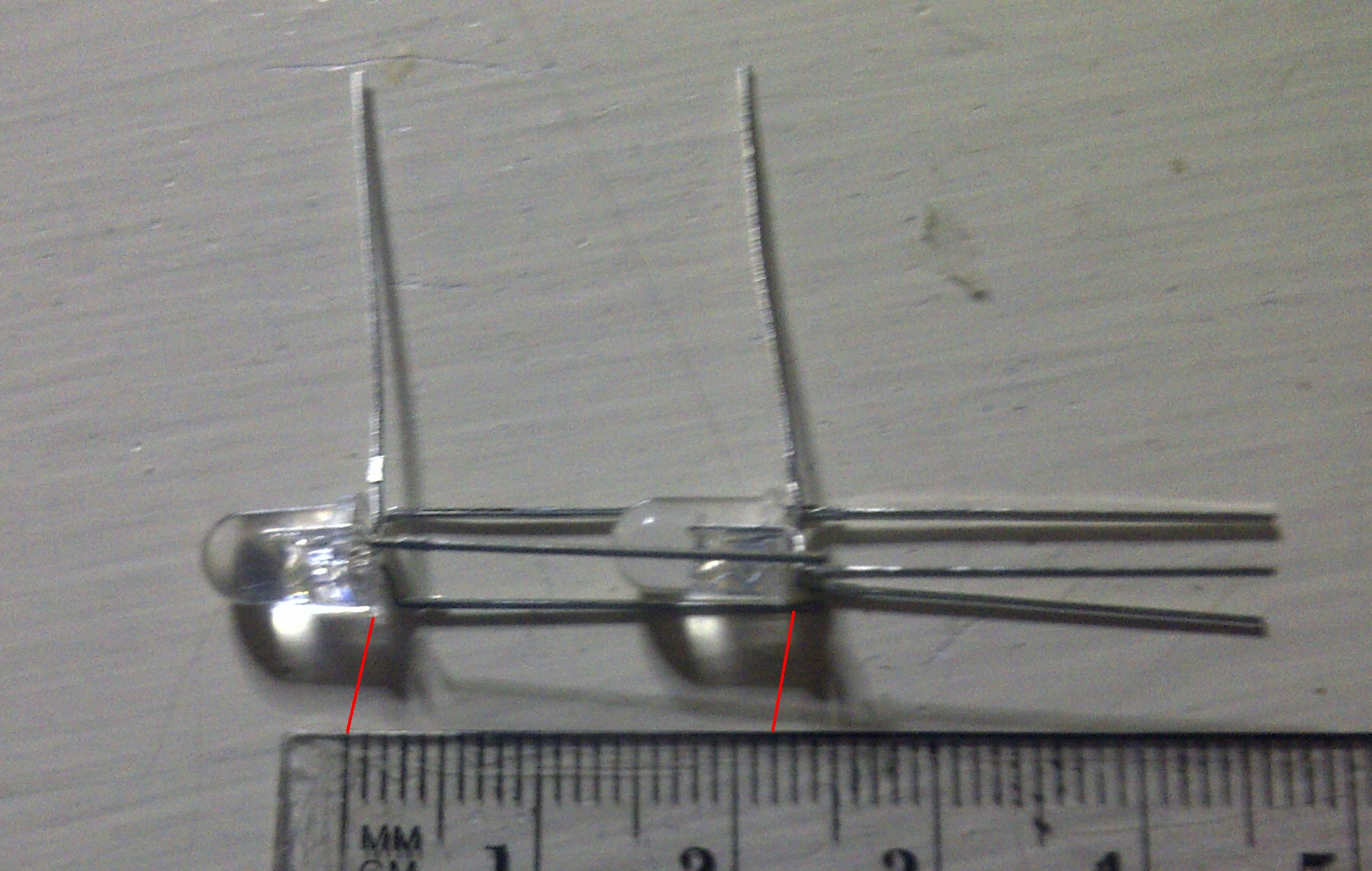
As suggested in the Instructable, having a Jig to hold the LEDs is very helpful! To design the Jig, place several bent LEDs together and measure the distance between them. In my case, it was 22mm, so I deducted an extra 0.5mm to allow extra overlap and decided on a 21.5mm spacing.
Mark up a grid of at least 2 x 8 on a thin timber board, centre-punch the intersections of the grid and then drill each hole. It pays to be as accurate as possible!
Note: Pre-test some drill bits in a separate scrap of wood to get a hole that the LED fits snuggly into. By drilling right through you will be able to push the LEDs out from the back if the fit is tight.
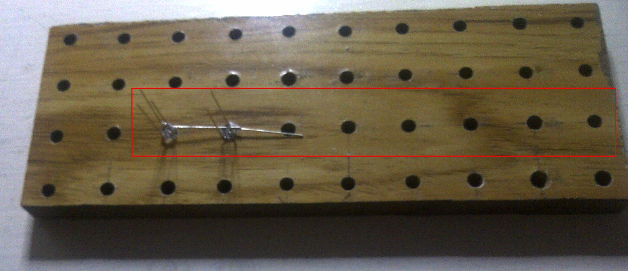
Then insert LEDs to form a row of 8 with the Cathodes overlapping as shown above and solder them together. Repeat this process until you have 64 rows of 8 ;-)
Note: If I do it again, I'd be a touch more careful lining up the holes and I'd go for a 21mm grid as the LED leg lengths are not always consistent and a bit of extra overlap is better than not enough!
I didn't take many photos of this part as it was just repeat, repeat, repeat...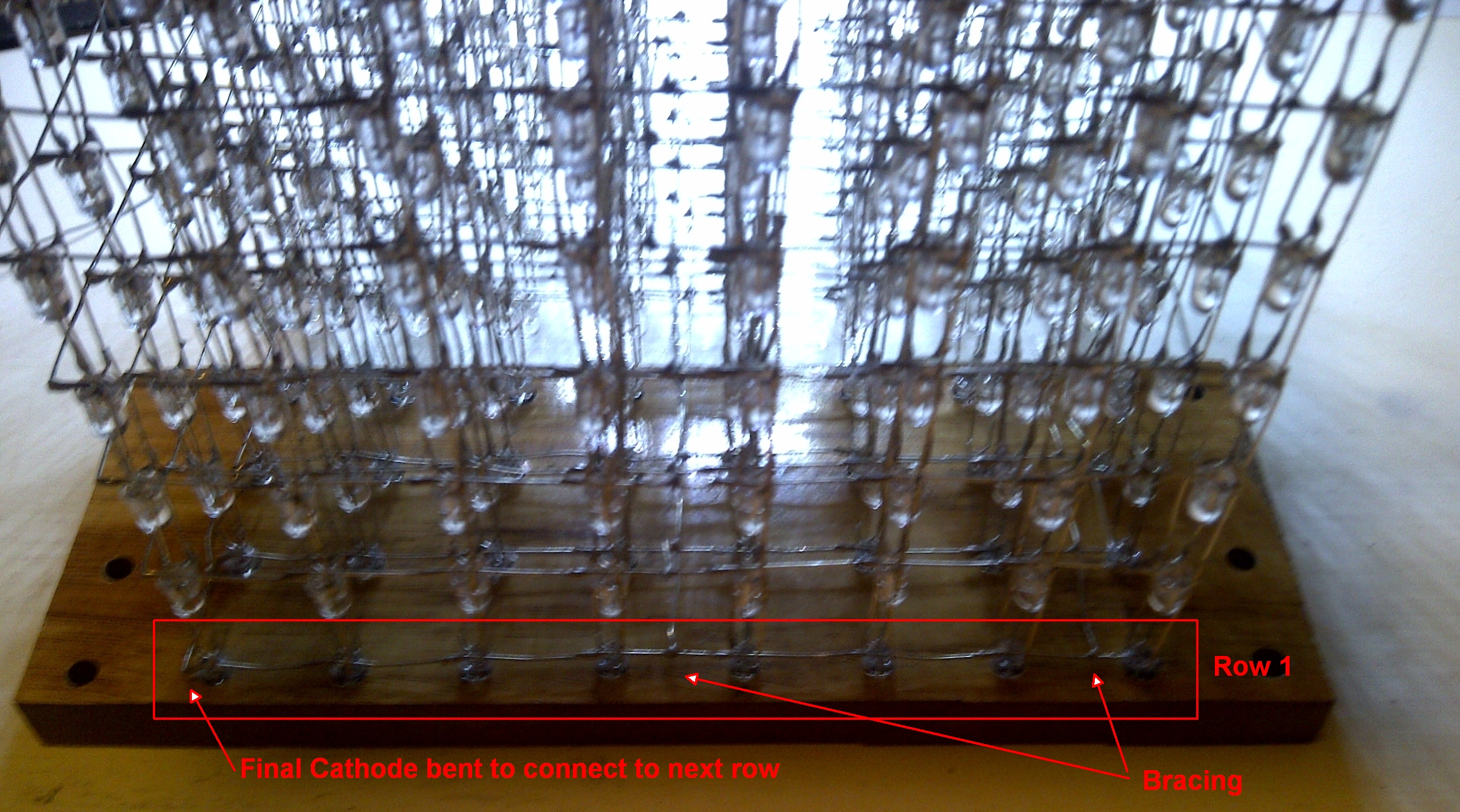
Construct 8 levels...
- Lay 8 rows across the Jig and bend the end Cathode to the left/right to connect the rows
- One Cathode will remain unconnected on each level to be the ground connection for the entire level
- Add some bracing to open end and in the middle [Slightly stretching a piece of stripped wire gets it straight!]
Test each level...
- Use a +5V supply with the positive to a 1k Ohm resistor and a fly-lead and the negative to a fly-lead
- Connect the negative fly-lead on the Cathode for the entire level [use the clip on the "extra pair of hands"]
- Test each LED by touching the [positive/resistor fly-lead to each unconnected pin
- Fix any problem LED before it gets embedded in the matrix!
Join the levels...
- Place the first layer on the Jig and sit the next layer on it so that the LEDs nestle in the first layers pins
- Use the "extra pair of hands" to hold each corner LED 21.5mm above the one below and solder all 3 pins [4 LEDs]
- Use a ruler to line up the 6 LEDs between each corner and solder all three pins of each [4 x 6 LEDs]
- Now repeat the process for the remaining 6 rows of 6 LEDs
Test each level combination...
- Same test as before, but with the negative fly-lead on the lowest Cathode [Row 1]
- Touching the positive/resistor fly-lead to each pin unconnected pin will now turn on the lowest LED [Row 1]
Having 3 pin connections per LED makes the matrix quire rigid as each level is added. Take care to keep the levels flat as individual adjustments will not be possible later, however minor adjustments to LED angles and vertical alignments will remain possible. With all 8 levels connected you will have a nice solid LED matrix and then you can fine tune the LED angles and vertical alignments.
Stop here if you just want a nice matrix (diamond?) ornament ;-)
Continue on to create a 3D animation masterpiece!
Now for the awkward part...
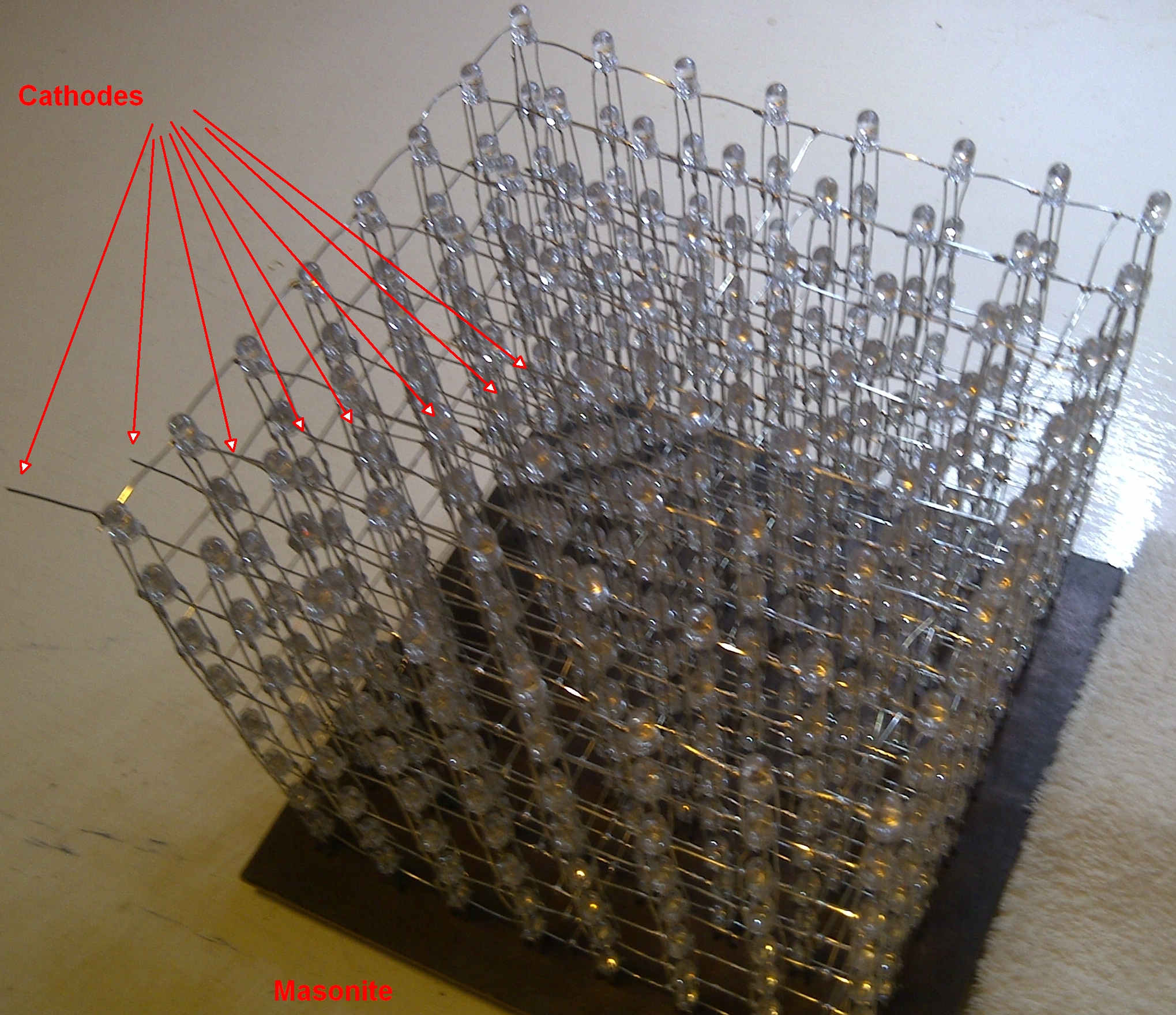
- Cut a square of Masonite to hold the matrix
- Paint the top of the Masonite (I just used a black permanent marker)
- Mark the grid on the back of the matrix so you know where each LED will be
- Drill three small holes at each point in the matrix to align with the 3 pins of each LED
- Mount the matrix on the Masonite with ALL PINS through the appropriate holes
Then some more soldering...
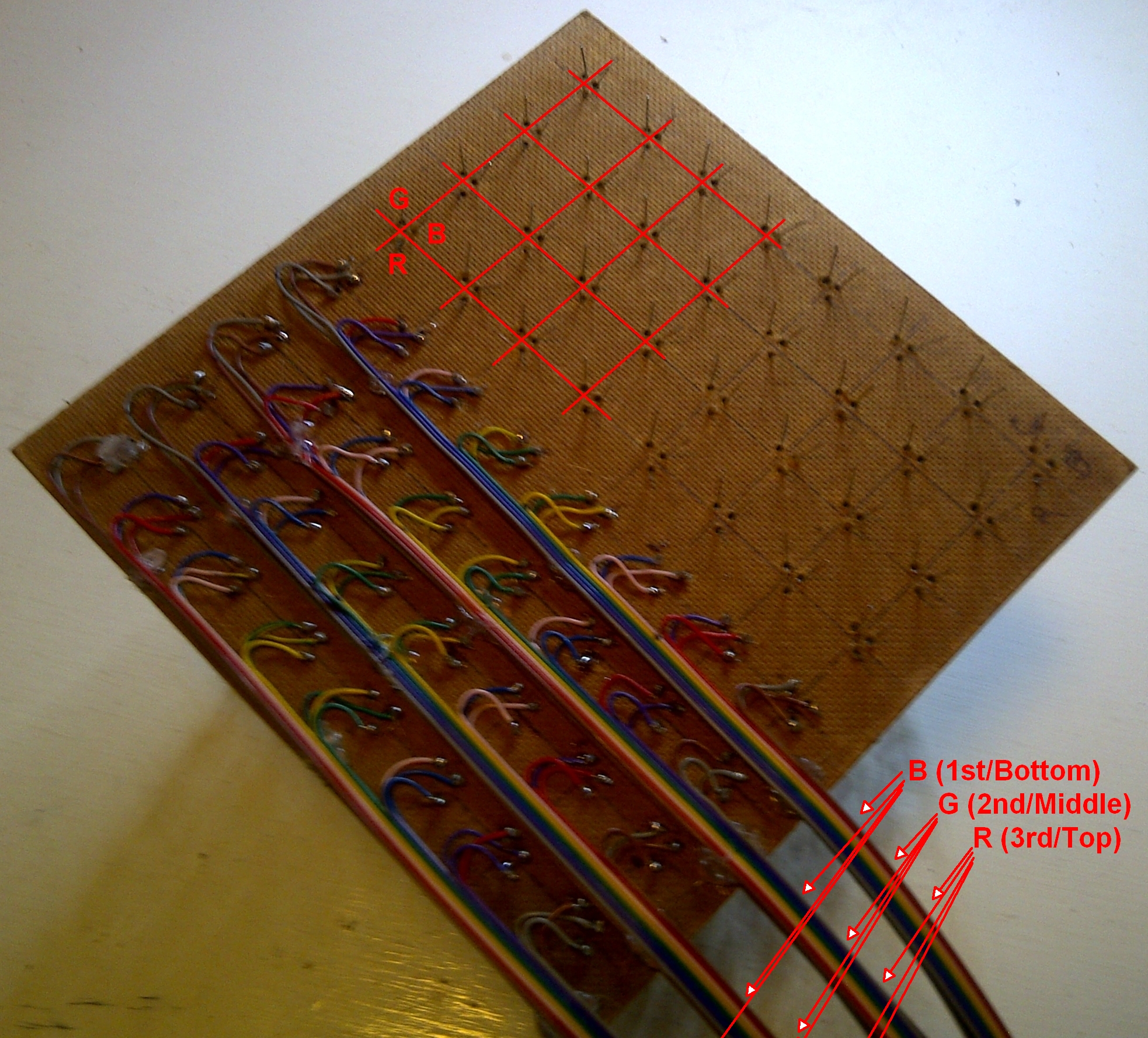
- Cut 12 x ~1m strips of 8 strand ribbon cable
- Place each strip with the middle along the row of LEDs and mark their positions (like below)
--------------------------------+---------------------------------------------------------------------
-------------------------------------+----------------------------------------------------------------
------------------------------------------+-----------------------------------------------------------
-----------------------------------------------+------------------------------------------------------
----------------------------------------------------+-------------------------------------------------
---------------------------------------------------------+--------------------------------------------
---------------------------------------------------------------+--------------------------------------
--------------------------------------------------------------------+---------------------------------
- Cut each strip in the designated spot so as to get 24 x ~50cm strips with nicely staggered ends to line up with the LEDs
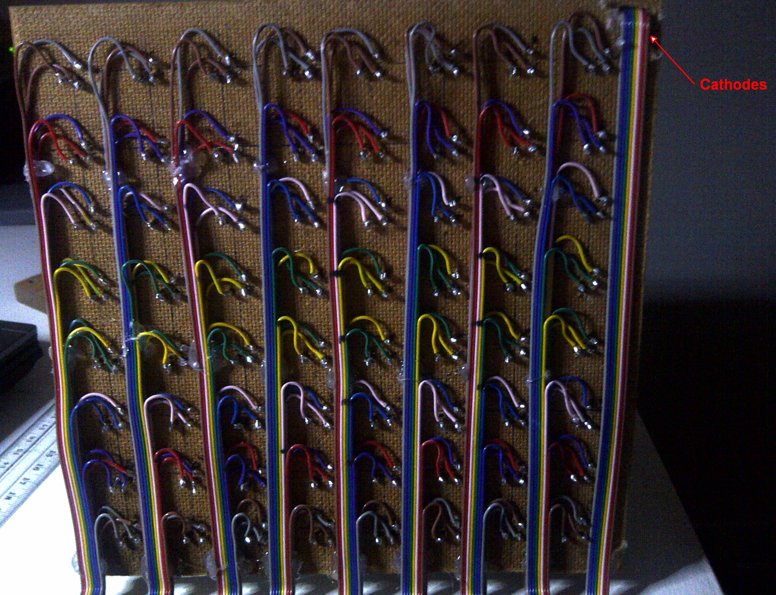
- Solder to the LEDs - Cable order is more important than the colourand the cable symmetry will help with identification!
- Use hot melt glue to hold each ribbon cable in place (prevents stress on the solder joints)
Then the final strip...
- Cut a small slot in the Masonite on the side where the Cathodes are
- Connect each cathode to a strand of the ribbon cable and thread it through the slot
- Use hot melt glue to hold the ribbon cable in place
Matrix complete!
On to the control!