Now to look at how the LEDs (Light Emitting Diodes) work...
- Like a Diode, current will only flow when there is a positive voltage difference from the Anode to the Cathode
- Light intensity depends on the amount of current that passes through the LED [20mA recommended for these LEDs]
- Too much current will cause the LED to irreparably fail [30mA for these LEDs]
- When operating, the "Forward Voltage" across the LED will be constant, regardless of the current through the LED
| Forward Voltage(V) |
Dominant wavelength(mm)K |
LuMen(LM) |
Reverse current(uA) |
Power Angle (deg) |
||||
| If=20mA | If=20mA | If=20mA | Vr=5V | |||||
| Min | Typ | Min | Typ | Min | Typ | Max | ||
| Red | 2.1 | 2.4 | 620 | 630 | 4000 | 5000 | 10 | 20-25 |
| Green | 3.0 | 3.4 | 520 | 530 | 7000 | 9000 | 10 | 20-25 |
| Blue | 3.0 | 3.4 | 460 | 465 | 5000 | 6000 | 10 | 20-25 |
We can now use the LED operating characteristics to design our circuit, taking into account the following three "Laws"...
- KVL [Kirchhoff's Voltage Law]: Sum of voltages around a circuit will equal zero
- KCL [Kirchhoff's Current Law]: Current into a connection equals the current out of a connection
- OHML [OHM's Law]: Voltage (V) = Current (I) * Resistance (R)
If we were to directly connect a 5V Supply to the Red portion of the LED, we would see some difficulty applying KVL. As 5V is supplied to the circuit, but the LED operating characteristics state that only 2.4V would be measured across the LED, there is a missing 2.6V in the circuit. As no component (LED, Supply, Lead, etc) is truely perfect, there is an incredibly small resistance in them that would normally be ingnored, however in this case it must be noted as this is where the 2.6V drop occurs! OHML tells us that the current flowing through an incredibly small resistance would be incredibly large * 5 and due to KCL, all this flows through the LED and as such, would easily exceen the 30mA allowed. To protect against this, we simply increase the resistance in the circuit so as to limit the current.
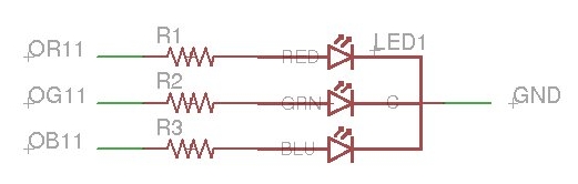
If we apply 5V at OR11, then 5V will be dispersed across R1 and the Red portion of LED1. As the Red portion of the LED has a typical "Forward Voltage" of 2.4V, the voltage across the resistor will be 2.6V. As the LED has a recommended current of 20mA, using KCL we want 20mA to flow through the resistor. Using OHML we can determine that a voltage drop of 2.6V would occur if 20mA passes through a resistor of 130 Ohms. Therefore R1 should be around 130 Ohms.
Repeating the logic for the application of 5V at OG11 & OB11, the voltage across R2 & R3 will be 1.6V and a voltage drop of 1.6V would occur if 20mA passes through a resistor of 80 Ohms. Therefore R2 & R3 should be around 80 Ohms.
Moving on, we now need to look at how the +5V will be supplied. Micro-controller I/O lines have two output states (ON = Supply = 5V and OFF = Ground = GND) and an input state (very high impedance = open circuit = no connection). For the LED to light, we need OR11/OG11/OB11 to receive 5V, so we can simply turn an output ON to light the LED and turn the output OFF (or no connection) to turn the LED off, thus they can simply be represented as a switched connection to +5V or GND (or no connection).
Finally, remembering that we built the LED matrix with the all the R, G and B lines joined together, if we connect the Cathodes directly to Ground, then ALL the interconnected LEDs would light at the same time which is not what we want. Instead, we need to connect just one Cathode to Ground at a time, thus ensuring that only one level can complete a circuit and therefore selecting exactly which of the interconnected LEDs will operate. This is now simply represented as a momentary connection to Ground.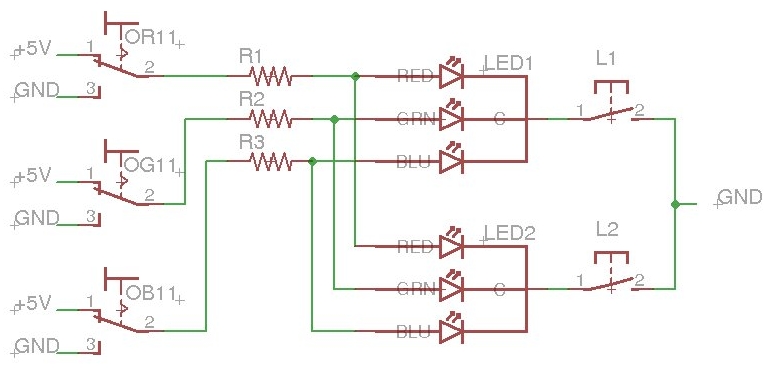
We now see a more accurate representation of the LED circuit with the control lines and the level switching. To imagine the final LED circuit, imagine the above actually has LED3, 4, 5, 6, 7 & 8 with L3, 4, 5, 6, 7 & 8, thus forming a single set of 8 LEDs (e: Row1, Column1, Levels1..8). Now repeat this circuit 8 times to achieve 8 Columns of the single set and finally, repeat those 8 Columns of the single set of 8 LEDs circuits another 8 times to get the 8 Rows of 8 Columns (ie: Imagine OR[1..8][1..8], OG[1..8][1..8] & OB[1..8][1..8] where the naming convention is O for Output, followed by R, G or B for the Colour, Followed by a value from 1 to 8 for the Row and finally followed by another value from 1 to 8 for the Column).
That's the basics, now we need to see how we can drive that many outputs, choose the components and connect everything up, many, many times!
Now that we have an LED matrix with (3x(8x8))x8 LEDs, how are we going to control 1,536 individual outputs, for a reasonable price?
As a nice little helper, there is an effect known as "persistence of vision" that helps! If you show each level, one after the other, at a fast enough rate, it will appear that ALL the LEDs are always on (ie: you don't notice them flick off). The construction already prepared for this by having a common cathode for each level (as opposed to the entire matrix or each LED), which means that we can drive one level at a time with only (3x(8x8))+8 outputs, which reduces the required output count to a much more reasonable 200.
Unfortunately 200 outputs is still a lot more than a single micro-controller has. This means we have to look at ways of synchronizing multiple micro-controllers (complicated and expensive) of we have find some way of multiplexing the outputs we do have in order to get the count down to a number that a single micro-processor can handle.
Basic Parallel Multiplexing with an M74HCT573...
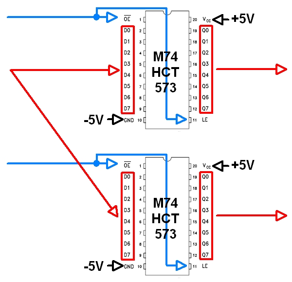
- Micro-controller has 8 output lines and 2 selection lines (ie: 10 outputs)
- The 8 output lines connects to both Latches, with one of the selection lines connected to each Latch
- Micro-controller drives the 8 output lines and selects Latch 1
- Latch 1 stores the 8 values
- Micro-controller then changes the 8 output lines and selects Latch 2
- Latch 2 stores the 8 new values
- Micro-controller clears the selections and leaves the 2 Latches showing 16 different outputs!
- 10 outputs on the micro-controller now appear to be 16 outputs
Extending to suit our project...
- Micro-controller has 8 output lines and 8 selection lines (ie: 16 outputs)...
- <same process as above, but with 8 Latches>
- 16 outputs on the micro-controller now appear to be 64 outputs
Multiplexing seems awesome, but there is an impact. Using a simplistic analysis, setting 16 individual outputs could be done in 16 processor clock cycles. Multiplexing of 8 outputs and 8 selection lines would require the micro-controller to set 8 outputs, raise the first selection line, lower it, set another 8 outputs, raise the next selection line and then lower it, and so on, thus effectively using 80 processor cycles. In the case of this example,16 processor cycles increases to 80! So there is a cost to be considered with multiplexing - the time it takes However, as modern micro-controllers now run at > 100 MHz, (ie: 100 Million cycles per second), 64 processor cycles execute in LESS THAN 1 microsecond. This will probably not impact our project, but as we increase the amount of multiplexing, we need to remain aware of the time impact.
Applying the parallel multiplexing example of 8 output lines and 8 selection lines to our project, we get 64 [ie: (8x8)] outputs from only 16 [ie: (8+8)]. This reduces our total need from (3x(8x8))+8 down to (3x(8+8))+8, which is really (3x8)+(3x8)+8 and make our new requirement only 56 outputs.
But wait, there's more! As we can set the 3 LED colours at the same time, they can share the selection lines, thus reducing the(3x8)+(3x8)+8 down to (3x8)+8+8, giving an improved output count of 40!
But wait, there's still more! The logically minded reader will realize that 8 selection lines, where only one is on at a time, can logically be reduced to 8 unique combinations of just 3 signals. Unfortunately that doesn't allow for an all-off state which is likely to be required to drive the latches, so we have to add an extra output signal for that, but hey, only needing 4 outputs is still better than the original 8! Therefore our final configuration of (3x8)+8+8 becomes (3x8)+4+4, giving an new output count of just 32!
Note: Given that there is a processor that has the required I/O, is fast and is well priced, there is no need to look any further. However if we look at it mathematically, the minimum number of individual output signals that would be needed to drive each level of 1,536 LEDs in an 3x8x8x8 LED matrix is 192, plus the level selection signals. Where only one LED is controlled at a time, 192 individual output signals could be derived from 8 outputs, giving an absolute minimum possible output count of 16 outputs to drive the whole LED matrix. Mind you, achieving the minimum would increase the complexity of the logic and the time that the processor would need to spend, so while it is nice to know, it would probably not be worth the effort!
From the multiplexing logic and the chip specification I was able to determine that the control board would need 3 sets of 8 chips. Each chip has 8 outputs that provides the Columns. Having a set of 8 chips gave 8 Rows of 8 Columns with each set of 8 chips providing one of the colours, thus forming 192 individual signals which was exactly the output count required for a single level.
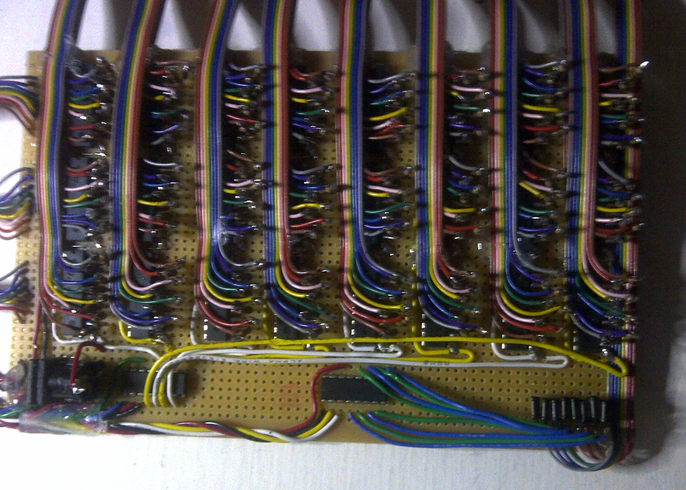
As I never actually bothered with a complete circuit diagram and I can't be bothered doing one just for the blog, I'll explain the circuit by describing the photos...
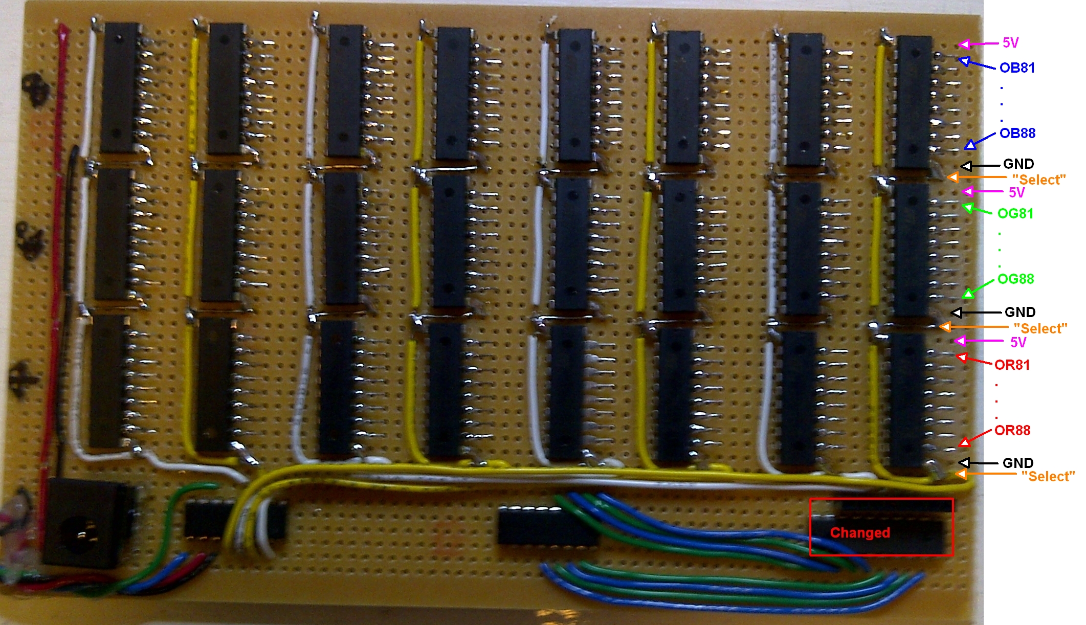
and the other side (note it is mirrored)...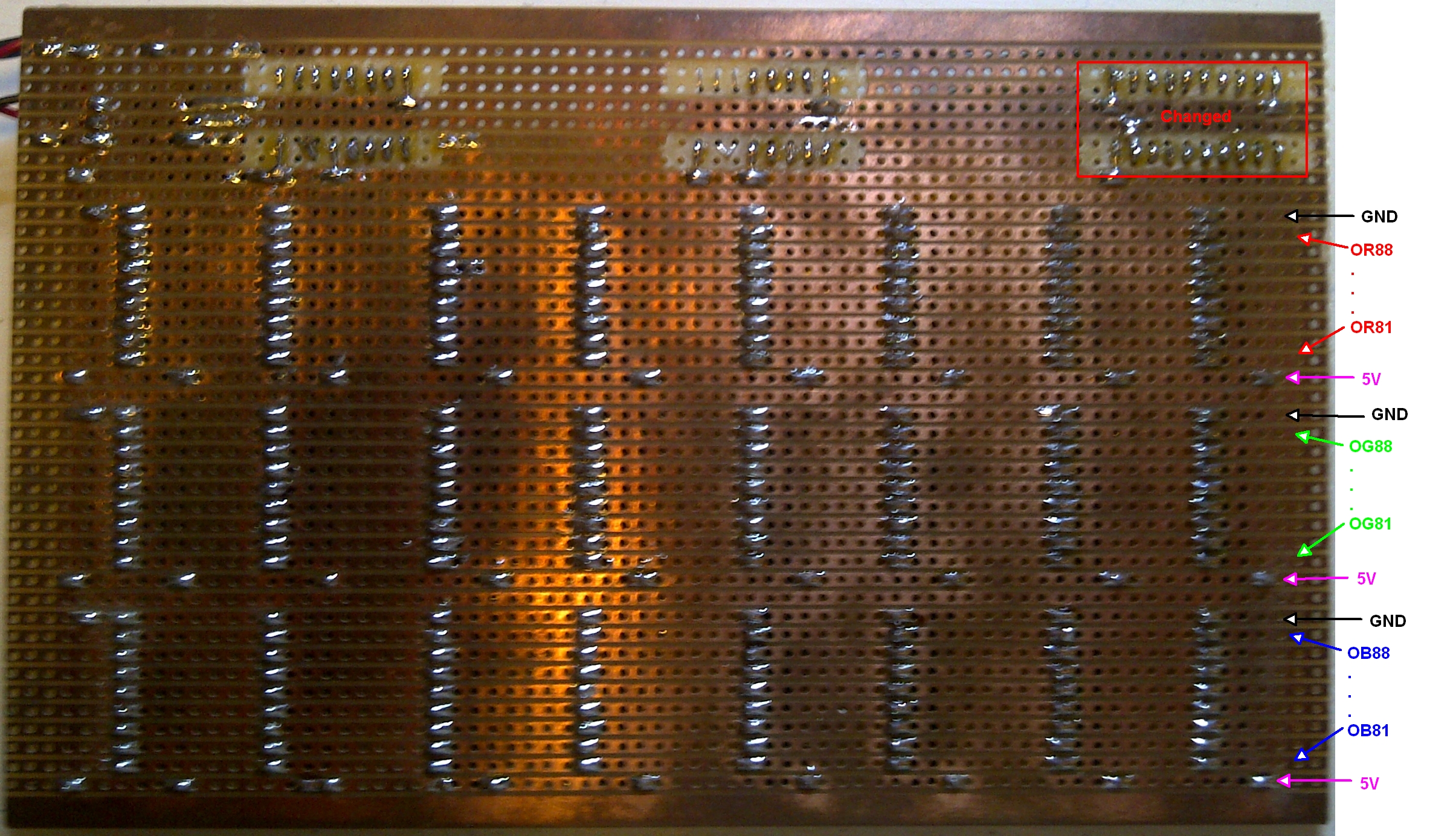
First off, from the LED circuit and the Multiplexing logic, I knew that I'd need to have 3 sets of 8 outputs feeding 8 latch chips (ie: 1 set of 8 columns x 8 rows per colour). Rather than running 3 sets of 8 wires and looping from chip to chip, I chose to use some easy to get strip board which is simply a pre-drilled circuit board that has copper tracks running across the back of the board connecting all the holes in a row. As each latch chip is identical, laying them out along the row allowed me to use the copper strips to connect the common signals and save a lot of time and mess. It is important to note that to do this I had to bend half the legs of the chips so they were horizontal to the board so they would not go through the holes and interfere with the circuit. This is NOT at all recommended by the manufacturers and can lead to pins breaking off the chips, but as you can see, it can be done. Here are my tips...
- Place the chip upside down on a flat surface
- Use long nose pliers to hold the pin near the body (at the shoulder ~1 mm from the chip body)
- Use a second tool to do the bend (only one way - never bend it back the other way)
- Once pins are bent apply some solder to them (the heat helps the metal repair and the solder adds strength)
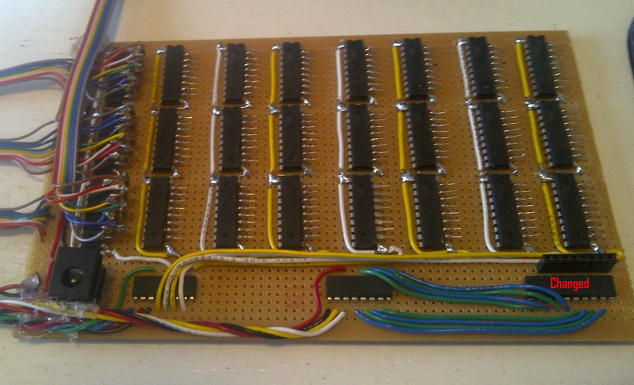
So as you can see, by doing it this way, the circuit is really neat and quite easy!
You should also be able to see the "Select" connection on the top image. This is not seen on the bottom image because the two pins on each chip that are connected as the "Select" line are both bent up. These I simply connected with some jumpers and you will also note that I connected the three colours so that they always trigger together. These "Select" lines come back to an M74HC259 logic chip that drives the 8 row "Select" lines individually based on 3 "Choice" lines and a "Control" line.
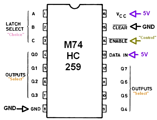
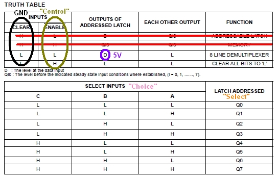
The operation now is fairly straightforward...
- We start by setting the 8 Red, 8 Green & 8 Blue outputs based on which LEDs we want on in a specified Row
- We also output the Row we want (eg: 000 for row 1 through 111 for row 8) on the "Choice" lines
- Then we output the "Control" line LOW to get the "Select" line we want raised
- The set of 3 "Selected" Latch chips now load the current set of 8 Red, 8 Green & 8 Blue outputs
- Finally, we drive the "Control" signal HIGH to stop the Latch looking at the outputs
- Result = The Latch now publishes the state of the outputs it just loaded!
And that is virtually the complete control board. The extra M74HC259 is in place to do the Level selection in the same way as we did the Row selection. but as the selection output is +5V when we actually want to provide a GND connection the selection output will need to go through an inverter (the "Changed" chip).
The final stage - Connecting the LED matrix to the output/control board...
The board now has the connections to the controller for the R, G & B outputs and the first row of LEDs is connected to the output pin through the appropriate resistor. Every second resistor was bent at a slightly different angle in order to make it less likely that there would be any chance of a short cicuit.
As enough connections were in place I was able to start some testing and I soon discovered that the LED brightness was not particularly good (and that was only with 8 LEDS in each layer instead of the final 64) .
I had failed to note that the inverter I used to turn the level on (connect the circuit to GND) could only handle 20 mA, however the Cathode connection was common to 64 LEDs with @ 20mA each. The inverted would potentially have to handle close to 4A of current! All I had to do was replace the original inverter with a 8 x MOSFETS (basically little solid state electric switches that current flows through when the selection input is on) and these could handle 4.2A of current each! I also re-connected the 5v DC input at a 90 degree angle so it would be accessible when I folded the LED matrix over the control board.
Then it was just a case of connecting the rest of the rows and I was finished!
On completion, the entire LED cube operated really well!